Project name: Building your dreams
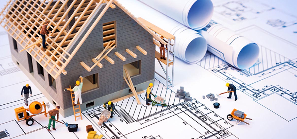
In architecture and building engineering, a floor plan is a technical drawing to scale, showing a view from above, of the relationships between rooms, spaces, traffic patterns, and other physical features at one level of a structure.
Dimensions are usually drawn between the walls to specify room sizes and wall lengths. Floor plans may also include details of fixtures like sinks, water heaters, furnaces, etc. Floor plans may include notes for construction to specify finishes, construction methods, or symbols for electrical items.
It is also called a plan which is a measured plane typically projected at the floor height of 4 ft (1.2 m), as opposed to an elevation which is a measured plane projected from the side of a building, along its height, or a section or cross section where a building is cut along an axis to reveal the interior structure.
Similar to a map, the orientation of the view is downward from above, but unlike a conventional map, a plan is drawn at a particular vertical position (commonly at about four feet above the floor). Objects below this level are seen, objects at this level are shown ‘cut’ in plan-section, and objects above this vertical position within the structure are omitted or shown dashed. Plan view or planform is defined as a vertical orthographic projection of an object on a horizontal plane, like a map.


